At 1.35 billion users and counting with an “always on” site, Facebook’s network infrastructure demands scalability and rapid evolution. Facebook’s network experiences machine to machine traffic several orders of magnitude larger than machine to user traffic, and this traffic is doubling at intervals of less than a year. Their machines also require extensive real-time cooperation to deliver a seamless end-user performance.
Despite Facebook’s improvements on the typical cluster architecture with their “reliable layer3 “four-post” architecture, offering 3+1 cluster switch redundancy and 10x the capacity of our previous cluster designs” several years ago, the design still suffered from limitations such as port density limiting cluster size and “maintaining an optimal long-term balance between cluster size, rack bandwidth, and bandwidth out of the cluster.”
Instead of trying to improve the current hierarchical network architecture types, Facebook decided to take a disaggregated approach and utilize small, identical units (server pods), similar to a layer 3 microclusters, that create a uniform network fabric with high-performance connectivity between all pods in the data center. All pods are served similarly to the 3+1 four post architecture for server rack TOR uplinks (with 4x40G uplinks each, 48 server racks in total). The fabric is simple, robust and highly scalable.
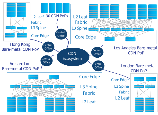
Spine Leaf Architecture In CDN Environment

To connect the pods to the building, spine switches are divided into four independent planes with up to 48 devices per plane. “Each fabric switch of each pod connects to each spine switch within its local plane” creating connectivity, reliability and connectivity, as all components are identical and interconnected.
Facebook did not stop with reengineering their network hardware, but also took steps to efficiently utilize this new architecture with virtualization and automation. Because all units in the fabric are simple, identical and interconnected, routing when a component hard-fails is not a concern; traffic can easily take another route to the destination. During troubleshooting, known issues are auto-remediated, new issues are investigated and the solutions programmed in for future remediation, traffic is routed around faults, and behavior and event data can be compared to isolate problems.
Heat maps are also accessible for high-level assessments and all other data on traffic is available at any time for analysis. Virtual clusters are also utilized for flexibility, allowing components to be deployed where and when they are available or needed. Facebook has already implemented this architecture at its Altoona data center, where it has increased intra-building network capacity by 10x and will easily grow to over 50x without changing port speeds.
Google’s Dataflow Aims to Simplify Engine Changes
When networks switch their native engines, they often have to scrap their weathered code to rewrite pipelines and adapt to new APIs to create newer code that may be riddled with bugs in the new operational engine. Google’s Dataflow will use a portable SDK and a programming model that will focus on the workload and not the capabilities of the specific engine being utilized. The Dataflow Java SDK is highly portable and connects to Apache Flink, Apache Spark, a Google implemented a single-node local execution runner and Google’s Cloud Dataflow service.
Real event time and real session semantics are the focus of the Dataflow programming, allowing the program to transfer seamlessly between engines despite different frameworks. It can also easily switch between batch and streaming execution modes. With the focus on defining data first, providing portability and a unified model with windowing, ordering and triggering information as well as access to open-source languages, libraries and tools, Google will be presenting its model to the Apache Software Foundation (ASF) Incubator project for collaboration and to be bundled with the Python SDK in the future.

